
Unmanned Express Delivery System
1. Hardware Selection and Configuration
The team has built a complete hardware system for the express delivery robot, consisting of a mobile chassis, a robotic arm, and computing & sensing devices. The parameters and functions of each component are clearly defined to meet the core requirements of grasping, transporting, and placing packages:
1.1 Mobile Chassis
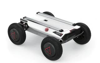
| Property | Specification |
|---|---|
| Dimensions | 820 × 640 × 310 mm |
| Wheelbase | 550 mm |
| Weight | 42 kg |
| Max Load Capacity | 50 kg (Meets package transport weight requirements) |
| Power | 24V Lithium Battery (30Ah/60Ah) + 2 × 350W Brushless DC Drive Motors |
| Steering | 150W Brushless DC Motor + 1:4 Reduction Gearbox |
| Steering Type | Front-wheel Ackermann steering |
| Steering Accuracy | 0.5° |
| Max Inner Steering Angle | 22° |
| Max Speed (No Load) | 4.8 m/s |
| Min Turning Radius | 1.9 m |
| Max Climbing Angle | 20° |
| Min Ground Clearance | 120 mm |
| Operating Temperature | -10 ~ 45°C (Adaptable to various competition environments) |
| Control & Security | Anti-collision beam, supports remote control (2.4G, max 200m) and command control |
| Communication Interface | CAN |
1.2 Robotic Arm


| Property | Specification |
|---|---|
| Degrees of Freedom | 6 DOF |
| Effective Payload | 1.5 kg |
| Body Weight | 4.2 kg |
| Repeat Positioning Accuracy | ±0.1 mm |
| Working Radius | 626.75 mm (High grasping accuracy) |
| Power Consumption | Max ≤ 120W, Comprehensive ≤ 40W |
| Communication Method | CAN (Compatible with chassis communication) |
| Operating Temperature | -20 ~ 50°C |
| Operating Humidity | 25% - 85% (Non-condensing) |
| Base Mounting Dimensions | 70 mm × 70 mm × M5 × 4 (Easy integration) |
| Hardware Limitation | Gripper max opening: 70mm vs. Target diameter: 65mm (Demands high algorithm accuracy) |
1.3 Computing, Sensing & Auxiliary Devices
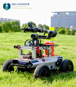
| Component | Description |
|---|---|
| Computing Core | 11th Gen Intel Core i7 NUC, ensuring algorithm execution and data processing efficiency. |
| Visual Perception | Hikvision industrial camera, adaptable to various lighting conditions, providing clear images for object detection. |
| Mapping & Localization | MID360 LiDAR paired with an Inertial Measurement Unit (IMU) for environmental mapping and robot localization. |
| Auxiliary Structures | 3D-printed Coke placement rack, tailored for specific grasping/placing target storage needs. |
2. Algorithm Design and Implementation
2.1 Technical Implementation: Navigation and Localization
The overall solution for autonomous navigation and localization is centered on ROS1, utilizing the FAST-LIO algorithm framework for mapping and localization, and the powerful Nav2 navigation stack for path planning and motion control.
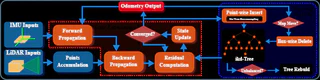
2.1.1 LiDAR-Inertial SLAM Mapping Based on FAST-LIO2
To achieve high-precision and high-robustness environmental mapping, we adopted the FAST-LIO2 framework, equipped with the mid360 LiDAR and IMU as core sensors.
Technical Principles: FAST-LIO2 is a tightly coupled LiDAR-inertial odometry framework. Its core technological advantage lies in abandoning traditional feature extraction steps in favor of a scan-to-map registration method, directly registering raw point clouds into the global map. This fully utilizes fine geometric features in the environment, significantly improving the accuracy and consistency of pose estimation. Additionally, it introduces the incremental k-d tree data structure (ikd-Tree) to maintain the map. Compared to traditional static k-d trees, ikd-Tree supports efficient incremental point cloud updates and dynamic rebalancing, greatly reducing computational resource consumption, allowing the system to achieve real-time mapping and odometry resolution at frequencies up to 100Hz with limited computing power.
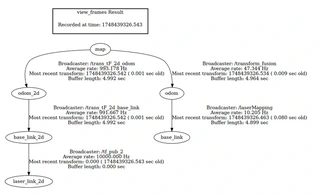
2.1.2 tf Tree Construction and Relocalization Based on Multi-Sensor Fusion
Our vehicle localization employs multi-sensor fusion of LiDAR, IMU, and chassis odometry, enhancing the robustness and accuracy of relocalization. To effectively manage and use localization information in the ROS1 framework, a standard coordinate frame transformation (tf) convention is adopted:
- map (Map Frame): A fixed world coordinate system acting as the global reference benchmark for all localization and navigation tasks.
- odom (Odometry Frame): A reference frame used to represent continuous and smooth robot motion.
- base_link (Robot Base Frame): A coordinate system fixed to the robot body.
Fast_lio_loc implements an innovative dual-layer localization architecture:
- High-Frequency Odometry Layer: Through tightly coupled LiDAR-inertial fusion of FAST-LIO, it generates local odometry information (odom -> base_link) at frequencies over 100Hz.
- Low-Frequency Global Localization Layer: Parallels a particle filter for global localization (map -> odom) at a frequency of ~0.2-0.5Hz, periodically correcting accumulated errors generated by the high-frequency odometry.
2.1.3 Navigation Based on ROS1 Nav2
We utilize the Nav2 framework, whose core is the nav2_bt_navigator node, adopting a Behavior Tree (BT) architecture to load and execute tasks.
- Global Path Planner (Dijkstra): Operating in Nav2’s Planner Server, it discretizes the global costmap into a grid network and performs graph searches to ultimately find the feasible path with the minimum cost.
- Local Path Planner (TEB): Running in the Controller Server, the TEB (Timed Elastic Band) algorithm frames trajectory optimization as a graph optimization problem via the g2o framework. The cost function produces a time-optimal trajectory considering path length, smoothness, distance to obstacles, and kinematic constraints.
2.1.4 Waypoint Navigation (Interacting with the Robotic Arm)
To achieve the closed-loop task of navigation → operation → navigation, an event-driven task coordination module was designed:
- Task Serialization: The waypoint sequence table is configured via YAML.
- Event-Driven Flow: Start target point -> wait for execution -> trigger robotic arm grasp/place message (publish
taskrelated topics) -> wait for completion (receiveTrueon the/finishedtopic) -> fetch next waypoint.
2.2 Technical Implementation: Robotic Arm Grasping and Placing Control
2.2.1 Coordinate System Establishment (Based on tf2)
Using tf2 to establish coordinate frames: chassis frame (baselink), robotic arm origin frame, end-effector frame, camera frame, and gripper frame.
2.2.2 Object Detection and Localization
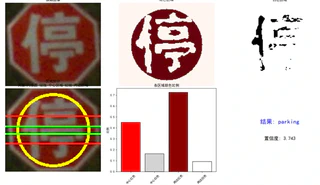
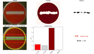
- Object Recognition Based on YOLOv11: Core technology based on YOLOv11s. Fine-tuned via transfer learning for specific targets in the competition arena, improving single-image prediction bounding box speed. Integrated secondary confirmation steps (color ratio analysis, etc.) to ensure correct judgments (e.g., parking, no_parking).
- Placement Localization based on AprilTag Variant Recognition: Efficiently calculates the 3D spatial position and orientation of the tags.
- Point Cloud Segmentation and EKF Fusion: Obtains point cloud data around targets using binocular depth camera triangulation. Fuses 2D position data identified by YOLOv11 with 3D point cloud data via Extended Kalman Filter (EKF) estimation and optimization to output precise world coordinates.
2.2.3 Robotic Arm Trajectory Planning and Control (Based on MoveIt!)
- Motion Trajectory Planning: Combined with the URDF model, MoveIt! translates high-dimensional tasks into bottom-layer collision-free trajectories (via RRT sampling algorithms).
- Collision Avoidance and Control: Sends adjusted control command parameters based on velocity and acceleration limits to the robotic arm’s low-level controller.
3. Reference Projects and Open Source
During development, we referenced:
- FAST_Lio2: https://github.com/Ericsii/FAST_LIO_ROS1
- Fast_Lio_Localization: https://github.com/HViktorTsoi/FAST_LIO_LOCALIZATION
- YOLO v11: https://github.com/ultralytics/ultralytics
- Piper SDK: https://github.com/agilexrobotics/piper_ros
- Nav2Catch: https://github.com/Skylarkkkk/nav2catch
4. Innovative Achievements and Project Highlights
4.1 Innovative Achievements
- Integrated cutting-edge SLAM with dual-layer localization architecture (FAST-LIO2 and dual-layer particle architecture) to achieve highly robust navigation and localization.
- Integrated advanced AI vision and multi-sensor fusion technology (YOLOv11, AprilTag, and binocular EKF optimization) to achieve precise and intelligent recognition and grasping.
- Implemented an “Algorithm-First” and task abstraction development strategy based on the ROS ecosystem, efficiently adapting to underlying hardware such as the AgileX Scout Mini / HUNTER SE chassis and PIPER robotic arm.
