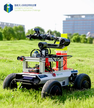
Unmanned Express Delivery System
1. Hardware Selection and Configuration
The team has selected and configured a complete hardware system for the express delivery robot:
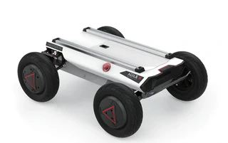
1.1 Mobile Chassis
| Property | Specification |
|---|---|
| Dimensions | 820 × 640 × 310 mm |
| Wheelbase | 550 mm |
| Weight | 42 kg |
| Max Load Capacity | 50 kg (Meets package transport weight requirements) |
| Power | 24V Lithium Battery (30Ah/60Ah) + 2 × 350W Brushless DC Drive Motors |
| Steering | 150W Brushless DC Motor + 1:4 Reduction Gearbox |
| Steering Type | Front-wheel Ackermann steering |
| Steering Accuracy | 0.5° |
| Max Inner Steering Angle | 22° |
| Max Speed (No Load) | 4.8 m/s |
| Min Turning Radius | 1.9 m |
| Max Climbing Angle | 20° |
| Min Ground Clearance | 120 mm |
| Operating Temperature | -10 ~ 45°C (Adaptable to various competition environments) |
| Control & Security | Anti-collision beam, supports remote control (2.4G, max 200m) and command control |
| Communication Interface | CAN |
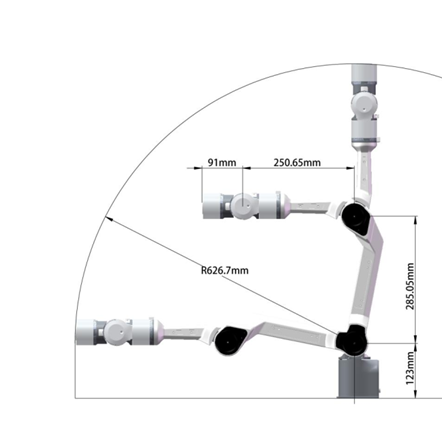
1.2 Robotic Arm
| Property | Specification |
|---|---|
| Degrees of Freedom | 6 DOF |
| Effective Payload | 1.5 kg |
| Body Weight | 4.2 kg |
| Repeat Positioning Accuracy | ±0.1 mm |
| Working Radius | 626.75 mm (High grasping accuracy) |
| Power Consumption | Max ≤ 120W, Comprehensive ≤ 40W |
| Communication Method | CAN (Compatible with chassis communication) |
| Operating Temperature | -20 ~ 50°C |
| Operating Humidity | 25% - 85% (Non-condensing) |
| Base Mounting Dimensions | 70 mm × 70 mm × M5 × 4 (Easy integration) |
| Hardware Limitation | Gripper max opening: 70mm vs. Target diameter: 65mm (Demands high algorithm accuracy) |
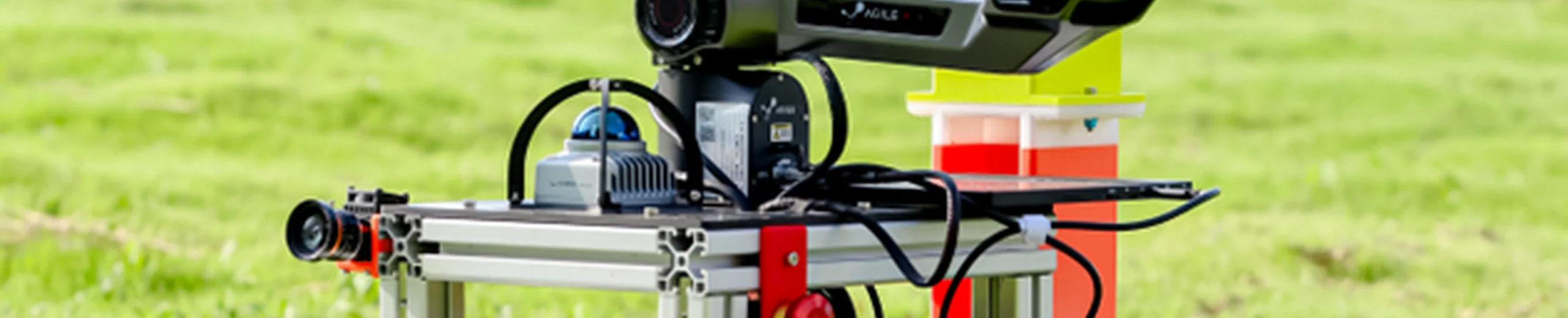
1.3 Computing, Sensing & Auxiliary Devices

| Component | Description |
|---|---|
| Computing Core | 11th Gen Intel Core i7 NUC, ensuring algorithm execution and data processing efficiency. |
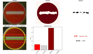
| Visual Perception | Hikvision industrial camera, adaptable to various lighting conditions, providing clear images for object detection. |
| Mapping & Localization | MID360 LiDAR paired with an Inertial Measurement Unit (IMU) for environmental mapping and robot localization. |
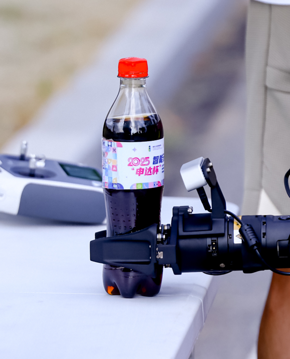
| Auxiliary Structures | 3D-printed Coke placement rack, tailored for specific grasping/placing target storage needs. |
2. Algorithm Design and Implementation
2.1 Technical Implementation: Navigation and Localization
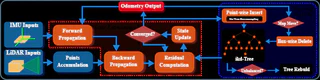
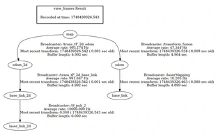
The overall solution for autonomous navigation and localization is based on ROS1, utilizing the FAST-LIO algorithm for mapping and localization, and the Nav2 navigation stack for path planning and motion control. FAST-LIO2 employs tightly coupled LiDAR-inertial fusion for high-precision mapping with mid360 LiDAR and IMU. Multi-sensor fusion (LiDAR, IMU, chassis odometry) constructs a tf tree for robust relocalization. Nav2 uses a Behavior Tree architecture with Dijkstra for global planning and TEB for local planning, optimizing trajectories for time, smoothness, obstacles, and kinematics. An event-driven module coordinates waypoint navigation with robotic arm interactions via YAML configuration and topic publishing.
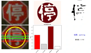
2.2 Technical Implementation: Robotic Arm Grasping and Placing Control
3. Reference Projects and Open Source
During development, we referenced:
- FAST_Lio2: https://github.com/hku-mars/FAST_LIO
- Fast_Lio_Localization: https://github.com/HViktorTsoi/FAST_LIO_LOCALIZATION
- YOLO v11: https://github.com/ultralytics/ultralytics
- Piper SDK: https://github.com/agilexrobotics/piper_ros
- Hunter SE ROS Driver: https://github.com/agilexrobotics/hunter_ros
